Quick Circuit Design Update

Circuit Design Update

I'm not sure this is the smartest thing to do, but to save myself making cables and connectors and such, I've moved some of the little daughterboards onto the main board:

The main board for the Office Chairiot Mk II is actually a shield for an Arduino Mega 2560. The original design was just a shield with a 5V DC switching regulator to power the various daughterboards and the connectors to connect them all to the pins of the Arduino. Now, I've moved the switch and button input board, the LED output board and the LCD control board onto the shield. The outer edge and center area of the shield will have headers to make connecting up the various external and interactive components of the system easier.

The new power board is simplified, has proper protection diodes and uses the new high-amperage wire lugs used on the motor controller. The new design also leaves much more copper on the board, so etching should go a little faster. The lugs are WAY more sturdier than the old screw-down copper terminals I was using. These lugs are soldered to the PCB and cannot twist and cause fires. No fire is good unless you've installed the flame thrower option.

Panel Graphics and Power Boards

Still waiting on the aluminum enclosure and panel from Liquid Metal Concepts, but in the meantime, I picked up the peel-n-stick decals for the control panels from Sign*A*Rama in Tempe:

For a test, I put the white-on-black decals onto the plastic panel I had laser cut earlier. Save for a few little air pockets, everything went on very straight and registration between the decals and the holes in the plastic panel was pretty decent.

Even though I'm not going to use the black plastic panel, I had nothing better to do with the black decals, but the concept works great. Black plastic control panels as an option seem doable. :)

Revision 3 of the power distribution board is finished and WAY more efficiently laid out than the previous ones.

I ordered some compact but high-amperage solderable lugs for the battery and motor controller wires. I contact the motor controller company (Dimension Engineering in Ohio) and asked for the part numbers on their excellent wire lugs. They AND the manufacturer responded ultra-fast and I had a bag full of them in no time. The lugs are strong and soldered onto the PCB, no bulky screws or big copper tabs required as compared to the copper ones I bought at Ace Hardware:

I Rearranged all of the two-pin jumpers into a single 8-pin header. Added flyback diodes on the coils and reverse protection diodes on the switch and LED lines (prevents turning on the two circuits out-of-order). Generally filled the power and ground planes out into open spaces (speeds etching, good practice). Here's the schematic, for giggles:

Hopefully I'll have the core of the systems plugged together in the next week or so, then I can bring the beast in for happy-fun-test-driving at LM.

Custom Control Panel Enclosure Update

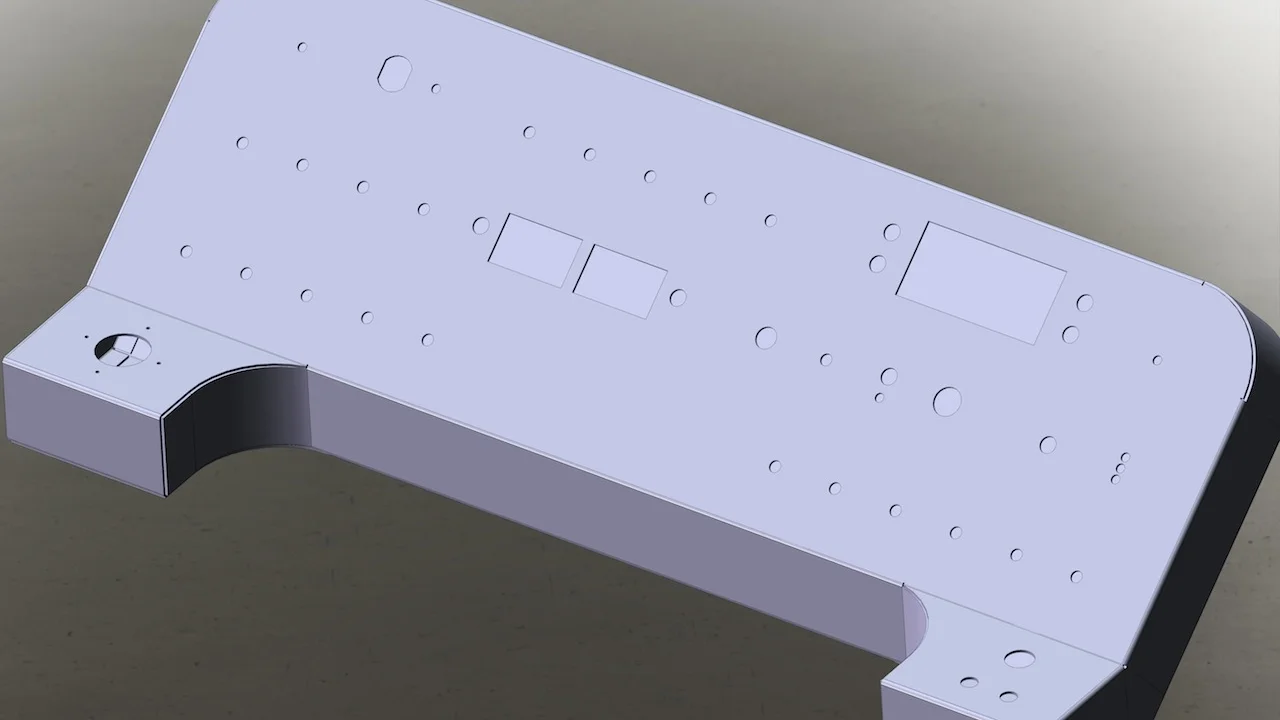
Liquid Metal Concepts here in Phoenix is helping make the aluminum enclosure for the control panel super-extra-rad with some fancy laser cutting and bending. Here are some renderings of the panel (pre chair attachment design)...

So, the cool kids use Solidworks. I'm a lowly Adobe Illustrator and Blender 3D putz. Solidworks does such an incredible job. #Jealous

The guys at Liquid Metal Concepts are really cool and I'd already started working with them before I learned that I could have brought all of my fab ideas/troubles to the LM Labs. So, next revision... There's still a sizable list of to-do items:

  • Body design, build
  • PCB fab and build (working on that right now)
  • Microcontroller software (working on it)
  • Replace the wooden chassis with a proper metal one

The next round of updates to this thing, which will likely happen at LM, will be a modular seat/cart system so that we can use a seat or a wagon cart on the chassis. Then I'd like to make the joystick detachable for use in mule mode. After that, start working on wireless control and eventually possibly line-following or indoor location services to have the chair figure out where to go on its own. #Skynet or #Chairnet

Looking forward to some cool pimpin' out on this baby at LM!

Another Update on Circuit Boards and Control Panel

Another update because I feel updatey today...

Here is a photo of the audio PCB and the Adafruit Class D amp breakout board and MP3+SD card breakout board:

Any of the sound effects on the Office Chairiot Mk II can be customized by simply placing an MP3 on the SD card. Which sound is tied to which effect is configured in the LCD menu system on the control panel and can be done on-the-fly.

Here is a 3D rough rendering of the aluminum control panel enclosure (chair and brackets not included in image, sadly):

The 2nd edition of the aluminum control panel is pictured below with the controls temporarily inserted. The 1st edition was laser-cut from ⅛" stock and was unnecessarily heavy and thick. The new one is .060" and much more like a real panel designed by someone who might know what they're doing. I don't, that's for sure.

The joystick (lower-left) (I'm left-handed, what of it?) and the horn/turn signal buttons panels will be level, the main control panel will be at a 30º angle.

The panel was originally going to be black plastic with white lettering. This is what the design would look like:

I opted fro aluminum instead because it reminded me more of a NASA space vehicle panel of some sort. I dunno. Aluminum is cool, so is shiny black plastic... Meh.

Here's what the white version of the panel design looks like (imagine it on a brushed aluminum surface, please):

I think the GPS fix indicator is missing in the upper-right, but you get the idear.

The two 12V AGM batteries for the drive system bookend the space for the motor controller, which I put in a hacked aluminum enclosure from Fry's Electronics, for now. Copper straps hold the batteries in place. The motors are mounted on adjustable wood cradles. The wheels are chain-driven and geared down. They're from MonsterScooterParts.com, as are the wheels and axles.

I'll be bringing the entire contraption down to LM shortly. The joystick is currently not connected to the motor controller, so driving it amounts to pushing it. :p

First Generation Power Relay Board

OK, been working on the circuitry and the actual panel for this silly thing nearly every morning. Right now, the control panel enclosure is being fabricated at a place here in Phoenix called, "Liquid Metal Concepts." The labeling/graphics overlay for the panel is being printed at Sign-A-Rama here in Tempe. They will peel-n-stick the control labels onto the aluminum. The labels are black printed on transparent something-something.

The first edition of the relay PCB that switches the main drive power (24VDC) and the accessories (12VDC) mostly worked OK. I forgot to add a couple of diodes around the relay coils to prevent voltages on the 24V coils when the 12V rail was switched on out-of-sequence. I may require some electrical engineering assistance on this to be sure the power is all OK. The relays are very beefy and to cover the potential current the motors may draw, I put two relays in parallel for the 24V rail.

Here's a picture of the board in testing:

The left relay is the 12V. The other two handle the 24V. To minimize heat, I'm using 6 AWG wire when it comes to the motors and the batteries.

The one thing that concerns me, and from what I'm reading around the web it's expected, is that the coils on the relays are getting quite warm (upwards of 130ºF). I know why, but I don't know if that's normal. I'm not sure that it shouldn't be normal, given the voltage and the current going through the coils, but still, they're too hot to touch for more than a second or so. I think I may put a 24VDC fan on the contraption for added happy fun times. Any thoughts?

I'll post some more stuff shortly.